| ||||||||||||
|
The
produced pipes have to go through a hydrostatic test at pressures imposed
by the standards.
;
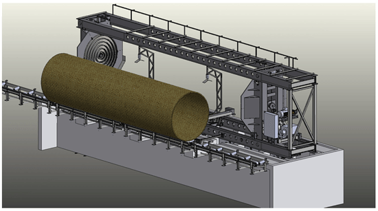
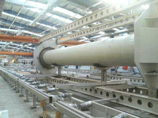
The HTU is
mainly composed of four I-beams carrying two heads (one moveable, one
fixed). The I-beams have holes spaced at 0,5meters to enable the locking
of the movable end for a safe operation. Hence it is possible to test
pipes that have lengths with a multiple of 0,5meters. The test heads are
installed on the fixed and movable ends.
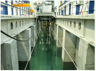
- The foundation upon which the two lower I-beams are installed. The foundation structure also serves as a reservoir for the unit. The filling pump is located in this reservoir. - Two movable skids that are used to carry, align and support the pipe within the HTU. To accomplish these functions, these skids are designed to move up, down, and longitudinally. The up/down movement of the skids are done hydraulically and the height control is done with a laser system. - Two pipe intake units that carry the pipe from the Pipe Transport System to the HTU and visa versa. To accomplish these functions, these units are designed to move up, down, transversally and longitudinally. The up/down movement of the units are done hydraulically. - The Drive System consisting of the Filling Pump, Pressure Pump, Release Valves. The movable end which carries the components of the drive unit is moved with a frequency controlled motor among the locking points.
All the operations of HTU are done and controlled through a PLC controlled operator panel located on the movable end.
| ||||||||||||
|
Profile |
Products |
Services |
References |
Contact |
Sitemap |


